Posted on

EMA Makes OrCAD CIS & CIP Training for Library & Component Management Free for Everyone

OrCAD Capture CIS and CIP Training

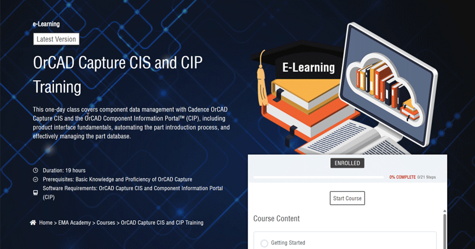
To celebrate the launch of OrCAD X and the fact that Cadence has included the very popular CIS option in their new OrCAD X PCB design suites we have decided to make our training course free to help customers leverage this new technology as they begin to adopt OrCAD X.

If that’s all you need to know you can access the free course here: OrCAD Capture CIS and CIP Training | EMA Design Automation (ema-eda.com) (just need to register…which is also free)

If you are looking for more information about what OrCAD CIS and CIP are and what they do for you read on…

What is CIS & CIP?

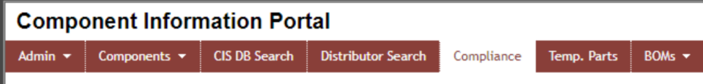
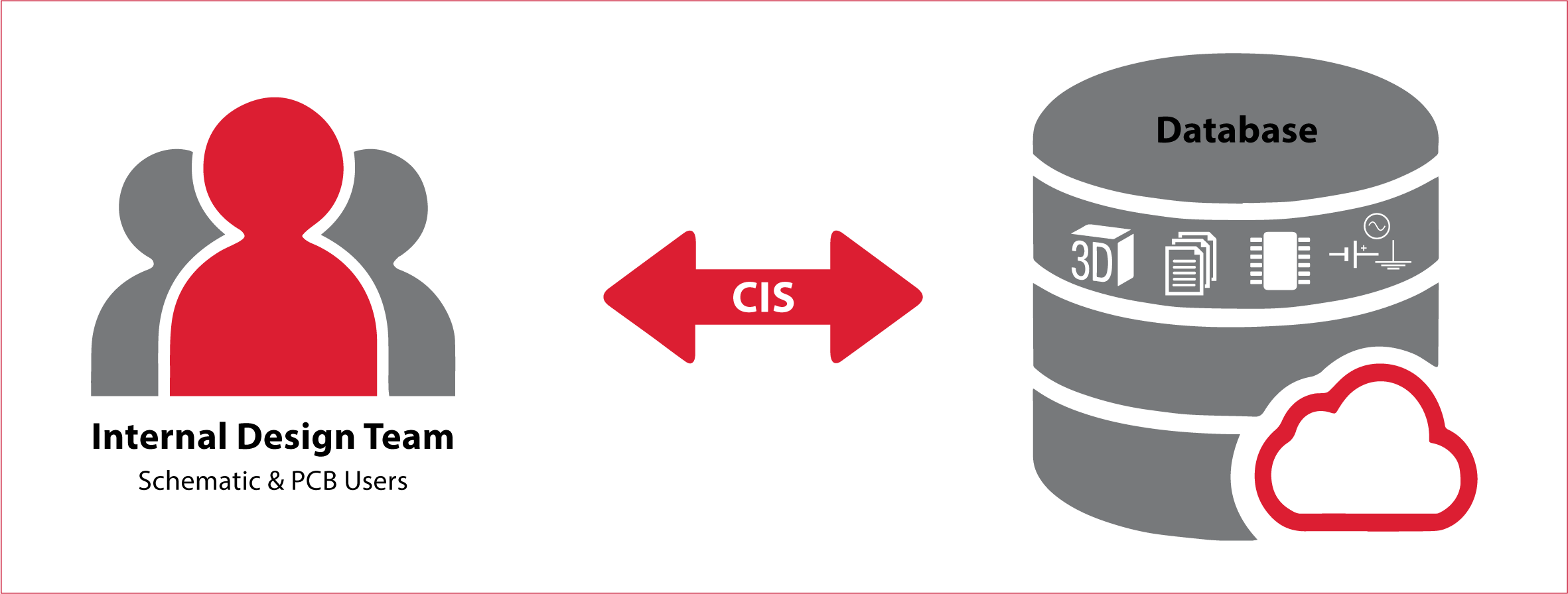
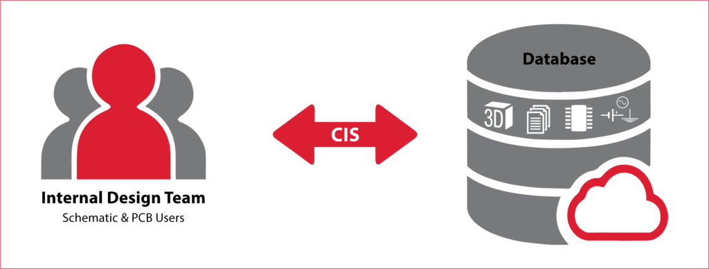
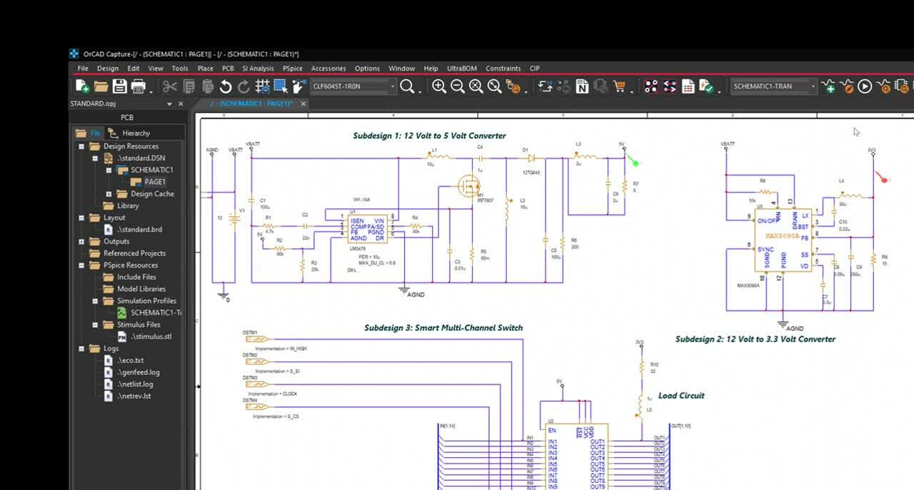
OrCAD CIS and OrCAD CIP stand for Component Information System and Component Information Portal respectively. What they do is enable your OrCAD environment to store, source, and manage your part library leveraging a relational database. This provides several significant benefits.

CIS enables the ability to connect OrCAD to a database which allows you to:

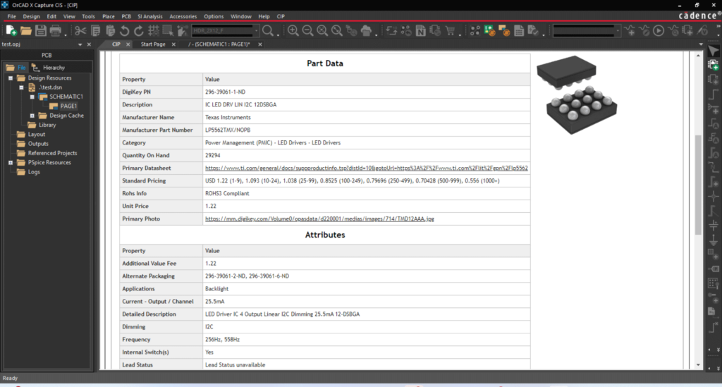
  • Integrate and centralize your component data
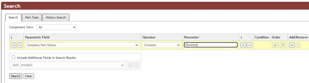
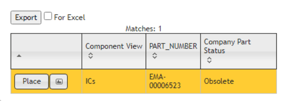
  • Provide parametric part search capabilities
  • Preview symbols and footprints before use
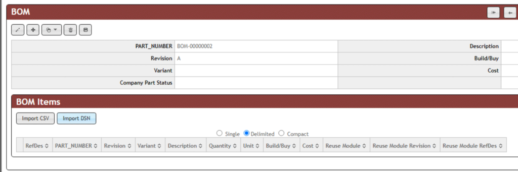
  • Templatize and configure BOM generation
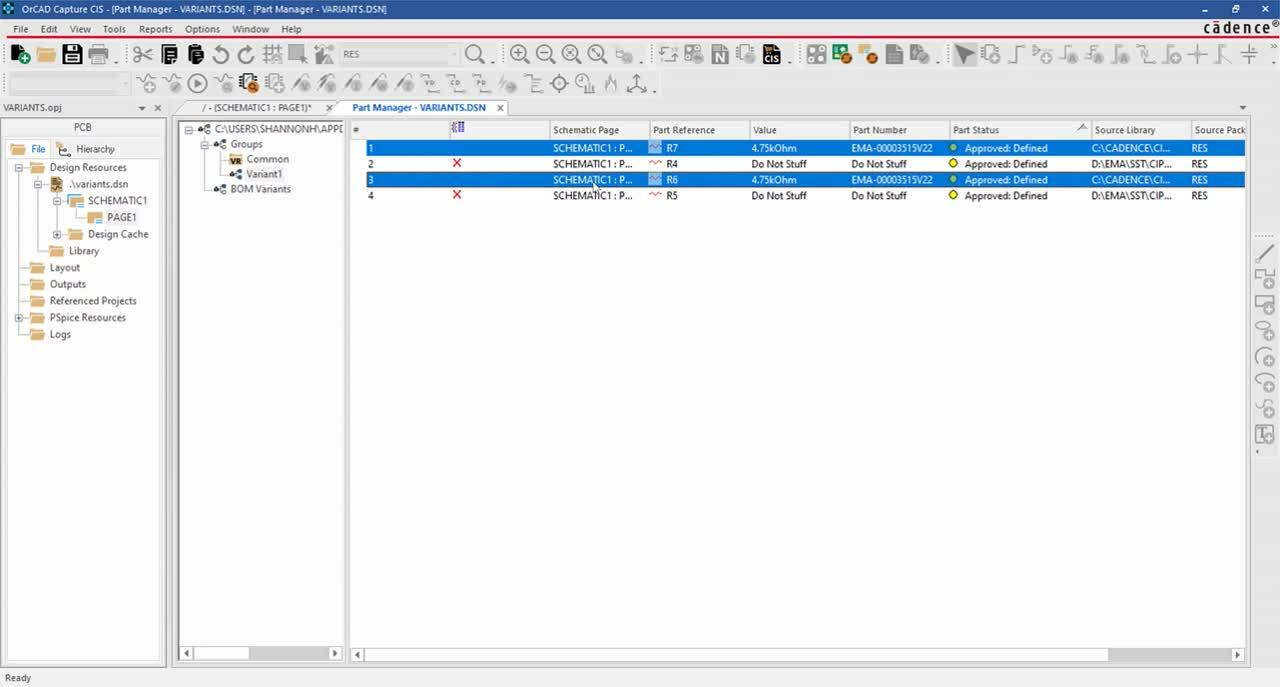
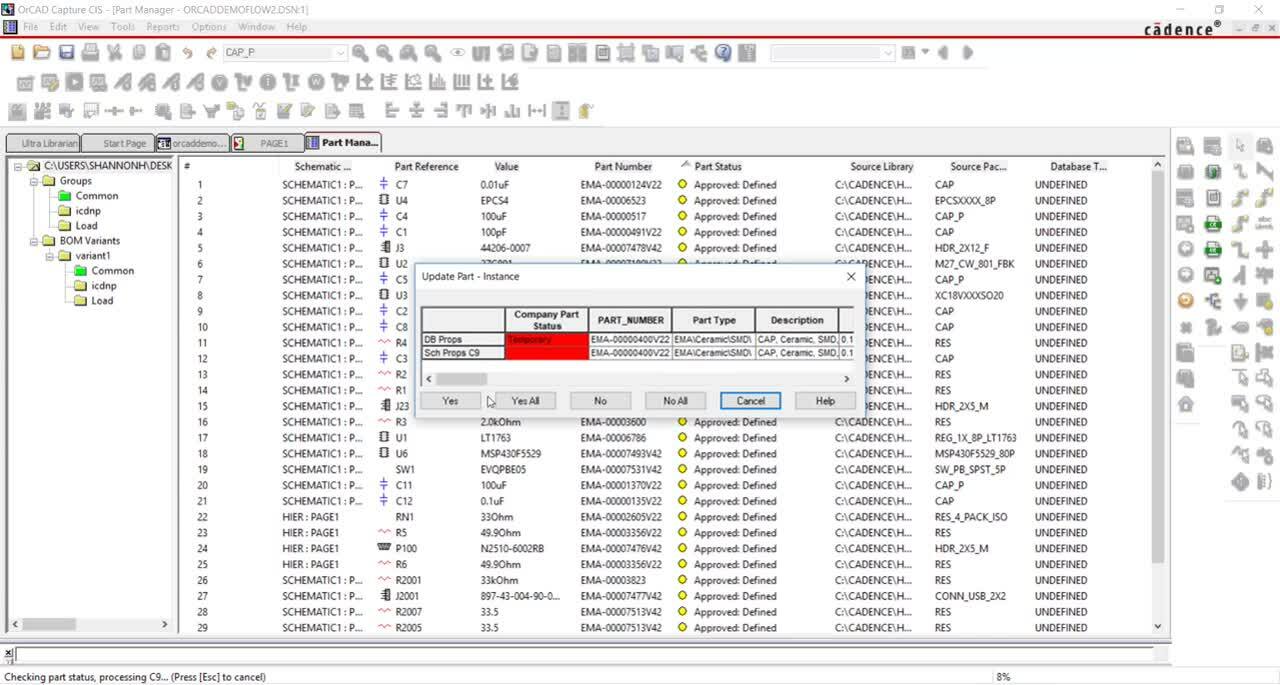
  • Integrate part management
  • Support design variants

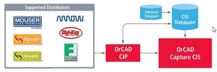
CIP provides the means of populating, managing, and automating this database so you can leverage it to the fullest including:

  • Search and import distributor parametric data for your parts (as well as keep this data updated automatically)
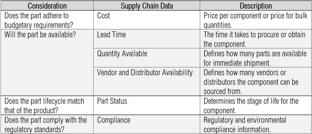
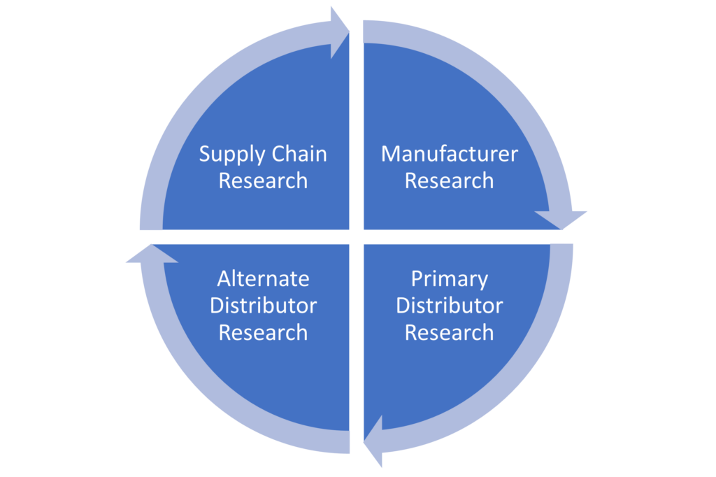
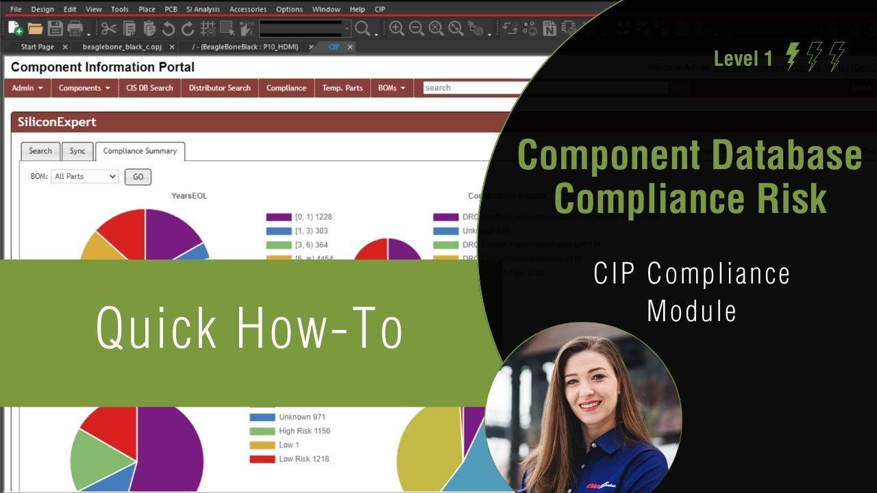
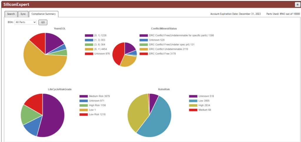
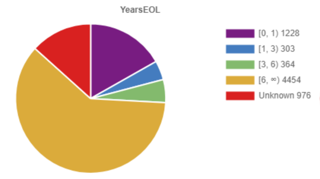
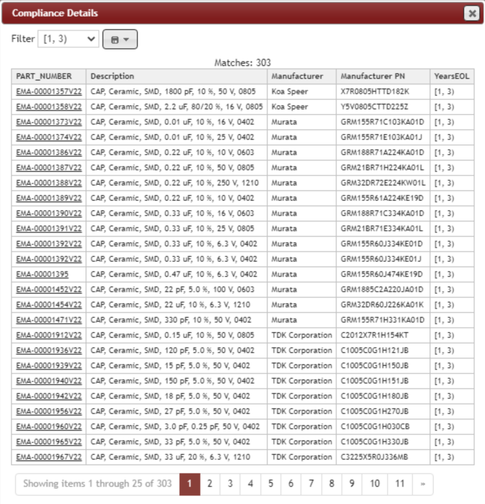
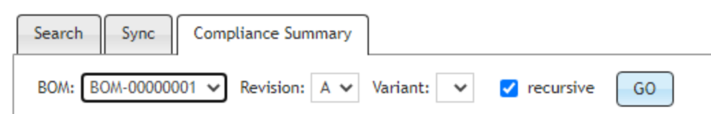
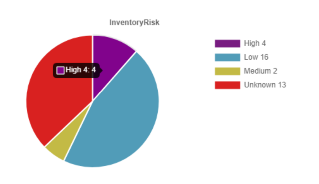
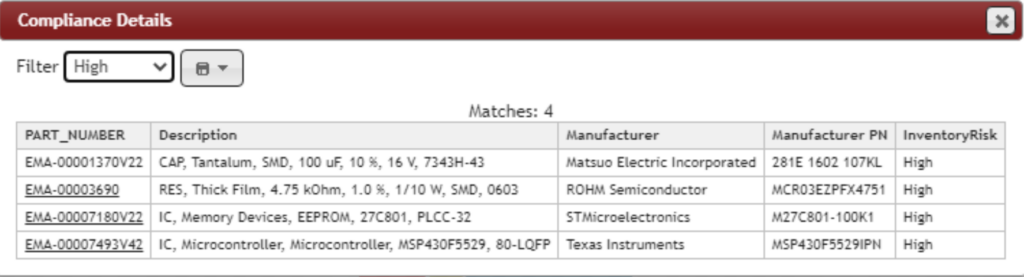
  • Connect supply chain data such as lifecycle, risk, cost, and compliance so you can easily make supply chain driven part decisions
  • Integrate with CAD library services such as Ultra Librarian to eliminate the need to build CAD models
  • Track changes to part status and other key metrics and trigger notifications off these changes
  • Identify multiple sources for parts to ensure availability
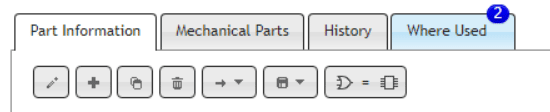
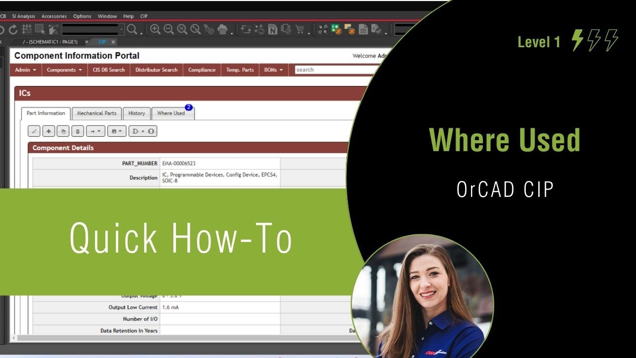
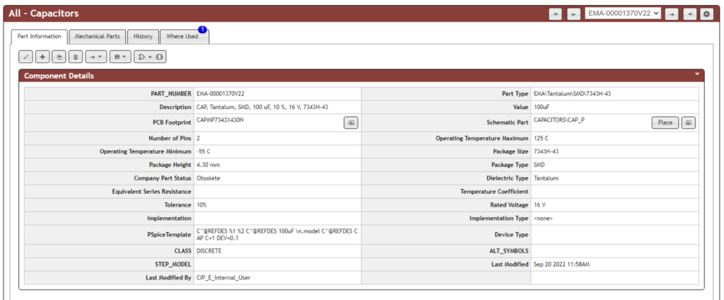
  • Leverage functions like ‘where used’ to quickly see the impact of part changes across all your designs (past and present)
  • Manage users and roles to ensure data integrity and traceability

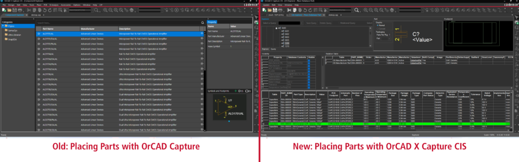
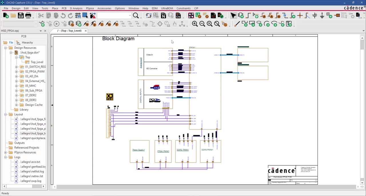
As you can see this is quite a powerful combination providing comprehensive part and library management capabilities directly inside the OrCAD design environment. These new capabilities mean there are now new ways to access and leverage your parts that you may not have been used to in OrCAD.

The OrCAD CIS and CIP training will help users get acclimated quickly to how to leverage these tools to their fullest.

Why Are We Making This Course Free?

This course was originally created based on requests from customers who had chosen to adopt this managed library flow. While this course has been available for a while, it was only applicable to those that owned these options for their OrCAD software. With CIS being made a part of the standard OrCAD X suite configurations this meant a lot more users were about to get access to this way of managing their libraries and data and we wanted to make sure this was a smooth transition for all users. Making this course free will (we hope) help users adopt CIS and the managed library approach which we have seen through years of experience means a more efficient and effective design process, and a happier customer.

How to Access the OrCAD CIS and CIP Training?

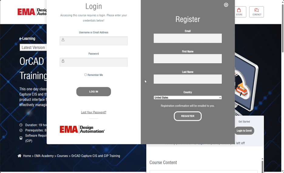
If you didn’t see above, the OrCAD CIS and CIP training course is part of the EMA Academy and is available to all users who have an active account (which is free) or who register for one. If you need to you can register right on the course page itself, just select login to enroll and complete the quick registration process.

Login and Register for the OrCAD Capture CIS and CIP Training

We hope customers will take advantage of this free training opportunity to help them learn how to leverage one of the key new features in the OrCAD X release.

Posted on

What is OrCAD X Capture CIS?

OrCAD X Capture is a well-known, industry standard software solution boasting limitless schematic design capabilities and expansive functionality to accurately document electronic design intent. OrCAD X Capture has a variation referred to as OrCAD X Capture CIS which now comes standard in the OrCAD X PCB design suites. But what is CIS and how does it differ from the typical OrCAD X Capture design environment? Whether you have upgraded to OrCAD X or are new to OrCAD X Capture CIS, let’s take a look at what exactly OrCAD “CIS” is, so you can leverage the additional functionality throughout your PCB design process.

What is OrCAD CIS?

OrCAD X Capture CIS

 CIS stands for the Component Information System. In addition to the standard OrCAD X Capture functionality for schematic designs, CIS provides a database connection. With CIS, you can achieve a link between your component database and your ECAD design environment. By establishing this link, you can source components from a centralized repository and synchronize designs with your component library to ensure up to date component information.

Key Features of OrCAD X Capture CIS

By incorporating the Component Information System (CIS) into your OrCAD X Capture design environment, additional features and capabilities can be leveraged when creating your schematic:

    • Integrated, Centralized Component Data
    • Obtain direct access to shared, centralized component data containing company approved symbol and footprint libraries within the schematic canvas.

    • Parametric Part Search
    • Search your component database based on parametric information to quickly find the desired part for your designs.

    • Symbol and Footprint Preview
    • View the corresponding symbol and footprint before placing a database part in your schematic design.

    • Efficient BOM Generation
    • Quickly create BOMs with predefined properties and automatic population of information based on your component database to create ready-to-order BOMs. Create templates to accelerate the BOM creation process and include multiple distributor options to ensure efficient purchasing and timely sourcing.

    • Integrated Part Manager
    • Ensure parts used in the schematic are up to date with an easy real-time status check of all components used in the design. A configurable color-coded status identifies components that are approved, temporary, and more directly in the schematic.  

    •  
    • Design Variant Support

      Create a design variant by defining differing component values and do not stuff components. CIS contains variant reporting to automatically generate a report including component differences between a core design and a variation as well as BOM Variant Support to easily select which design variation should be used to create the Bill of Materials.

    Utilizing these key features during schematic creation results in several benefits to your PCB design process.

    Benefits of OrCAD X Capture CIS

    The ability to access a component data management system within your ECAD design environment provides designers with an efficient method to use verified and approved components for their designs. This alone has an immense impact on the speed and accuracy of documenting your electronic design intent. In addition, the features and capabilities of OrCAD X Capture CIS improve your design process by:

      1. Creating Consistency

        Without a component database, typically users manage parts on individual machines or shared servers. With CIS, all team members are pulling component data from a centralized database of approved parts, creating consistency and reducing errors. The integrated part manager ensures data remains consistent between your design and the component database with seamless synchronization.

      2. Saving Time

      •  
      • With a component data management system, each user isn’t responsible for the creation and management of parts. This reduces duplicate efforts for creating the same parts, symbols, and footprints as well as reduces the time spent verifying component data.
      •  

      3. Making Informed Part Decisions

        Centralized component data, part parametric search capabilities, as well as a symbol and footprint preview allow designers to review all component information up front within their CAD environment to quickly select the best component for the design.

    Achieving a streamlined design environment with OrCAD X Capture CIS can greatly improve team collaboration and your PCB design process; however, there are some considerations and questions you need to ask yourself to configure a component data management system that sets your team up for success. 

    Component Database Considerations

    To implement a component data management system that can fully realize the benefits of OrCAD X Capture CIS, there are some questions that must be considered:

      • How do you setup your database?

      • How do you determine and implement a database schema?

      • How do you determine and implement a part number scheme?

      • How do you map existing symbols and footprints to components and parametric data?

      • How do you update the information found in your component database?

      • How do you manage alternate manufacturers or distributors?

      • How do you ensure data integrity?

    These questions must be addressed to develop a plan for successfully implementing and managing PCB component data. If the above questions are not considered upfront, managing the contents of your database may be problematic- this is where OrCAD Component Information Portal (CIP) can help.

    Efficiently Managing Component Data with OrCAD CIP

    CIP Flow Diagram


    Component Data Management with OrCAD CIP


    The benefits of OrCAD X Capture CIS can be easily realized and enhanced with the addition of OrCAD Component Information Portal (CIP). OrCAD CIP provides an easy-to-use interface and database management tools to populate and update your component database. OrCAD CIP fulfills many component database considerations to achieve a comprehensive component data management solution with:

        • Starter Component Database Schema and 5,000 Part Starter Library

        • Automatic Part Numbers

        • Automatic Population of Parametric Information

        • Detailed Part History

        • Bulk Import of Existing Components

        • Real-Time Pricing, Availability, and Compliance Information

        • BOM Import/Export and Revisioning

      By incorporating OrCAD CIP into your OrCAD X Capture CIS environment, you can accelerate component database creation and enhance your component data management system. See how the functionality of OrCAD CIP can streamline your PCB design process here.

      OrCAD Capture and OrCAD Capture CIS

      OrCAD Capture

      Industry leading schematic capture environment for first pass success

      Limitless Schematic Design

      Hierarchical Design Support

      Large Pre-Built Library

      Component Management

      Complex Rule Support

      Integrated Simulation

      Design Variants

      Intelligent PDF Output

      Comprehensive Schematic Design at Your Fingertips

      Shorten your product design cycle with embedded rules, seamless PCB and simulation integration, automated design rule checks, and an integrated component library directly within your schematic canvas.

      Electronic Rules Check
      and Embedded Rules

      Easily define and embed design rules in the schematic to drive the PCB layout and clearly communicate vital functionality requirements. The customizable ERC Matrix allows for easy definition of errors and warnings when testing connections between pins, hierarchical blocks, and hierarchical ports. Verify schematic accuracy with real-time design rule checks for common electrical, physical, and simulation errors.

      Productivity-Focused
      Environment

      Efficiently create designs from simple block diagrams to complex hierarchical, multi-sheet schematics with OrCAD’s comprehensive design environment. Work at peak efficiency with automated design cache for recently used components, reference designator assignment, annotation, and back annotation. Designed with your preferences in mind, OrCAD’s customizable workspace and toolbars along with its open design framework, TCL scripting, and app support, create an easily configurable user experience.

      Expansive Component Library

      Design efficiently with a standard library of commonly used schematic symbols including power, ground, off-page connectors, no connects, hierarchical blocks, and ports. Easily select parts from an extensive library of commonly used components including discretes, FPGAs, Opamps, Microcontrollers, and more. With integration to Samacsys and Ultra Librarian, easily view live parametric data for millions of components and quickly incorporate verified symbols, footprints, and 3D models into your design. Direct connection to your component database within the schematic canvas guarantees company-approved parts are selected for designs.

      Clear and Accurate Reporting

      Streamline design reviews with an intelligent PDF of the schematic and interactive identification of components, nets, connectivity, and more. Guarantee component purchasing and assembly with customizable component properties and Bill of Material creation. Accelerate BOM creation with predefined properties, templates, and automatic population of information directly from your component database to create zero-touch BOMs.

      Seamless PCB and Simulation Integration

      Seamlessly communicate design intent with one-click netlisting and PCB creation. Confidently pass information between the schematic and PCB with bi-directional publishing and automatic identification of changes. Perform early analysis on your critical high speed nets with built in signal integrity analysis. With integrated access to PSpice, easily simulate circuit behavior directly within the schematic; no design translations necessary.

      Variant Support

      Easily support world-wide production and manage component variations for multiple manufacturing and design requirements with OrCAD. Define differing component values or do not stuff components and efficiently communicate assembly changes with color-coded schematic information, variant bill of materials, and variant reports.
      Streamlined Schematic Entry
      Hierarchical and Multi-Sheet Schematics
      Block Diagram Support
      Snap Functions and Grids
      Efficient Connectivity and Automatic Wiring
      Automated Component Alignment and Distribution
      Differential Pair Definition and Management
      Graphical Design Compare
      Comprehensive Project Hierarchy
      Customizable Workspace and Open Design Framework
      Automatic Titleblocks
      Automated Design Cache
      Comprehensive Schematic Search and Bookmarks
      Picture and Documentation Support
      Built-in Translators (Altium, Mentor, Eagle, more)
      Integrated Access to Component Database
      Integrated Part Manager
      Part Status Notificaition
      Design Variant Support
      Color-Coded Variant Component Display
      Libraries, Symbols, and Models
      Schematic Symbol Editor
      Library of Common Schematic Symbols
      Library of Common Components
      Millions of Symbols, Footprints, and 3D Models
      Customizable Component Properties
      Easy Association of Supporting Models
      Centralized Component Data
      Parametric Part Search
      Temporary Part Management
      Symbol and Footprint Preview
      Streamlined Temporary Part Creation
      With CIP
      Easy New Part Introduction
      With CIP
      Automatic Population of Parametric Information
      With CIP
      Automatic Part numbers
      With CIP
      Part History
      With CIP
      Association of Simulation Models, Symbols, Footprints, Datasheets, and Documents
      With CIP
      Starter Component Database Schema
      With CIP
      5,000 Part Starter Database
      With CIP
      Bulk Import of Existing Components
      With CIP
      Access to Component Database Through Web Browser or OrCAD
      With CIP
      Streamlined Component Searches
      With CIP
      Customizable Permissions for Component Library
      With CIP
      Supply Chain Insights
      Real-Time Pricing and Availability
      With CIP
      Real-Time Compliance Based Search
      With CIP
      Multi-Sourcing Support
      With CIP
      Integrated Distributor Information (Digi-Key, Mouser, Arrow, and More)
      With CIP
      Where-Used
      With CIP
      Cloud Enabled Services
      Cloud-Based Workspaces
      Managed User Roles
      Customizable Permissions
      File Management and Version Control
      Integrated Part Authoring and Management
      Promoted Library of Symbols and Footprints
      Automatic Population of Parametric Information
      Association of Simulation Models, Symbols, Footprints, and Datasheets
      Comprehensive Rules and Checks
      Electrical Design Checks
      Physical Design Checks
      Simulation Design Checks
      Custom Design Checks
      Customizable ERC Matrix
      Define Design Check Exemptions
      Real-Time Design Rule Checking
      Embedded Rules
      Net Property Definition and Management
      Electrical Rule Definition and Management
      Physical Rule Definition and Management
      Spacing Rule Definition and Management
      Streamlined Integration
      PCB Layout Creation and Automatic Netlist Generation within your Schematic
      Real-Time Design Synchronization
      ECO Support
      Cross Probing and Cross Placement of Components Between Schematic and PCB
      Integrated Spice Simulation
      Signal Integrity Simulation
      Accurate Reporting
      Standard PDF Output of the Schematic
      Intelligent PDF Output of Schematic
      Automatic Netlist Generation
      Customizable Bill of Material (BOM)
      Automated Zero-Touch Bill of Material (BOM) Creation
      BOM Templates
      Relational BOM Support
      BOM Variant Support
      Variant Report
      Easy BOM Import/Export
      With CIP
      Easy BOM Revisioning
      With CIP

      Get the Most Our of Your Schematic Design Tool

      Get the most out of OrCAD Capture with these additional integrations. OrCAD Capture Component Information Portal (CIP) simplifies part management and selection with an easy-to-use interface integrated directly within OrCAD Capture. OrCAD Engineering Data Management (EDM) allows you to manage all aspects of your design data and ensure seamless team collaboration with features such as revision control and library management. Get control over the supply chain with access to critical part information and identify unorderable, obsolete, and high-risk parts directly in the schematic using SE Connect BOM Risk. Constraint Design EE effortlessly manages your high-speed PCB Design rules at the schematic level.

      OrCAD PCB Designer

      See how OrCAD PCB Designer seamlessly integrates OrCAD Capture and PCB Layout for the ultimate design experience

      OrCAD PSpice Designer

      Learn how OrCAD PSpice Designer can easily verify schematic functionality directly with OrCAD Capture.

      SCHEDULE A DEMO

      Component Data Management with OrCAD Capture CIS and CIP

      Data Management Training Courses

      OrCAD Engineering Data Management

      OrCAD EDM (Engineering Data Management) is a collaborative environment which enables teams of engineers to work together on a Cadence PCB project and easily manage all the associated files and revisions. This course will provide you with the necessary knowledge required to effectively manage your team within the OrCAD EDM Environment. New users will learn how to navigate the tool as well as tips and tricks on how to get the most out of the product. This course takes approximately 5-6 hours and is available as a one-day Virtual Training.

      Includes an OrCAD Certification Opportunity.

      It is recommended that students have a pre-requisite knowledge and proficiency in OrCAD Capture Schematic editing.

      What you will learn:

      • How to assign roles based on tasks
      • How to set up users, assign privileges
      • Template and project best practices
      • How to manage libraries and assign symbols to team members
      • Adding parts to master libraries
      • How to activate OrCAD EDM within PCB Editor so all PCB and related files become a part of EDM-managed projects

      OrCAD Certification

      Users who register for select classes gain access to our OrCAD certification test.  Certifications are designed to help students demonstrate their mastery of OrCAD products.

      OrCAD Component Data Management​

      This one-day class will cover component data management with Cadence OrCAD Capture CIS and the OrCAD Component Information Portal™ (CIP), including product interface fundamentals, automating the part introduction process, and effectively managing the part database.

      It is recommended that students have a pre-requisite knowledge and proficiency in OrCAD Capture Schematic editing.

      What you will learn:

      • Manage parts and symbols in a relational database
      • Assign user privileges
      • Track historical changes of active and legacy parts
      • Manage the integrity of active and historical parts
      • Use distributor searching to locate necessary parts
      • Align new part introduction with corporate protocols
      • Create and formalize new parts
      • Link legacy data to approved parts
      • Swap out parts using Link Database Part
      • Finalize and document the design
      • Manage variants

      Register for a Class

      Posted on

      Real-Time Part Management with OrCAD Capture CIS

      Keeping the schematic in sync with the part database can be a tedious, time-consuming task. OrCAD Capture CIS streamlines this process with:

      • Real-time part information
      • Color-coded part status
      • Automatic synchronization of the schematic and component database
      • Automatic identification of component differences
      • Color-coded components on the schematic and component database

      Efficiently manage parts for your PCB designs and ensure schematics are up-to-date with accurate component information with real-time part management in OrCAD Capture CIS.

      OrCAD Capture CIS

      OrCAD Capture CIS

      Accelerate your design process and lower project costs with an integrated component information system.
      Request Info

      Centralized Component Data

      Provide centralized, shared access to your component library across the organization to avoid redundancy and ensure available and approved parts are being used.

      Parametric Part Search

      Search for best fit components based on your unique criteria including, value, tolerance, cost, and status.

      Streamlined Libraries

      Avoid redundancy and reduce errors with on-the-fly mapping of parametric data to your schematic symbols.

      Temporary Part Management

      Don’t let adding new parts slow the design process down. Enable designers to work with placeholder parts that can be replaced with approved versions once ready.

      Design Variants

      Easily manage board assembly variations without having to maintain duplicate schematics or manually edit individual BOMs.

      Get The Specs

      Additional information and details are available in the OrCAD Capture CIS datasheet.

      Download Datasheet

      Get A Quote

      Find the version and licensing agreement that best fits your needs and budget.


      Request a Quote

      Make Component Data Your Competitive Advantage

      According to the Aberdeen Group, best-in-class companies see their component data as a way to build differentiation from the competition.


      73%

      Consider their component libraries as critical IP


      90%

      Employ a centralized library management strategy

      Component Data Webinar

      Learn more about our component data management solutions. Attend our free on-demand webinars.
      View the Webinar

      Looking to Automate Component Data Acquisition and Management?

      Enhance the OrCAD CIS with real-time access to external component data sources, permissions management, and the ability to manage your data from a web browser.

      Learn More

      Built on OrCAD Capture

      OrCAD Capture CIS is built on the industry standard schematic editing platform, OrCAD Capture. Learn why OrCAD Capture is the most popular schematic capture program on the market today.

      Learn More

      Component data at your fingertips

      Let us help you get started today.

      Request Quote

      Posted on

      Design Begins and Ends with Your CAD Library

      When looking at PCB design, one of the most important yet often overlooked pieces of the design process is the CAD library. Not only is the library a requirement to define and implement the design, but the library also serves as the foundation for driving ordering and DFM readiness for your product when it is being manufactured.

      With this kind of impact on both the beginning and end of the design process it is critically important to have a good understanding of how PCB CAD libraries are structured, the data available in them, and how that is used to support the design process.

      What Functions Does the CAD Library Serve?

      Logical and Physical Building Blocks

      Most people associate PCB CAD libraries with the symbols, footprints, and 3D models that are used as digital representations of the components being designed onto the PCB. The goal of the library in this respect is to provide a reusable, accurate digital model of your parts to save you time by making it faster to define and implement your PCB projects. For PCB footprints, it is critical the library is accurate and based on the real part dimensions, as this is what will be used as guide when DFM checks, and analysis are performed before the board is manufactured.

      Data for Component Ordering

      The CAD library often (or should) contain the data needed for purchasing such as:

      • Manufacturer part number
      • Procurement source(s) – often distributors like Digikey or others
      • Price – ideally updated on a regular basis to reflect current pricing

      Including this data in your component library will help create complete, ready-to-order BOMs and facilitate timely purchasing.

      Supply Chain Driven Component Selection

      Not only do you need to know if this is the right part for your design’s technical needs and that you have the needed digital representation to use in your CAD tools, but you also want to make sure this part can be purchased and used- when and where you need it. Supply chain data needed to help determine this includes:

      • Part lifecycle status
      • Potential alternates
      • Risk factor
      • Lead time
      • Compliance data (such as RoHS, REACH, etc.)

      Team Productivity and Reuse

      A key component of the library is as a productivity enabler for the entire team (both the immediate PCB design team as well as manufacturing and procurement). By centralizing your CAD library data, ideally making it searchable and extractable, you enable multiple stakeholders in the design process to leverage this information to drive decisions from part selection through manufacturing and ordering. With this kind of impact, its import to get your library environment setup for success from the beginning.

      How to Ensure Your CAD Library is Setup for Success

      Below are some initial tips to help ensure your CAD Library can function as needed to meet your design, manufacturing, and procurement requirements.

      Treat Your Library as a Key Part of the Design Process

      The library should be treated as a key productivity enabler for the design of PCBs. Your library is a key part of your process that can lead to significant productivity gains for the whole team. A good library won’t just “build itself” (although there are tools and services to help). The investment in time is paid back several fold.

      Keep Content Fresh

      The amount of change in the electronic component market is staggering. Parts are constantly being discontinued and new ones added. It is important to keep the data in your library current with these changes, so you don’t inadvertently design in parts that are not available or do not meet the regulatory criteria of your intended end markets. Integrating with distributor data in real-time is one way to help you keep things fresh.

      Build Process and Standards to Ensure Data Integrity

      Since the library often supports multiple people and teams, that means there will be lots of users who may or may not have a full understanding how the library is configured and what should and should not be changed. It is important to set process and standards for use to maintain data integrity. If possible, employ version management and role-based permissions to drive consistency and data integrity.

      Make Your CAD Library a Competitive Advantage

      Building an efficient and effective CAD library takes some upfront planning but the results make the investment worth it, many times over.  To help ease the process and accelerate library deployment, tools like OrCAD CIP exist to speed up and automate your library setup and management.

      EMA has been building and deploying PCB CAD library solutions for customers for over 25 years. Learn more about our library management solutions including ready-to-deploy tools like OrCAD CIP.

      How to Utilize Where Used Functionality in OrCAD CIP

      Many of today’s electronic products leverage a company’s intellectual property, reusing known-good circuits and making modifications to accelerate the design process; however, with fluctuations in the supply chain and a rapid component lifecycle, ensuring all the components needed are available and purchasable can be time-consuming. With Where Used functionality in OrCAD CIP, you can easily identify every design a component is used in to easily identify and replace unavailable components.

      This quick how-to will provide step-by-step instructions on how to use where used functionality in OrCAD CIP.

      How-To Video

      Open in New Window

      Uploading a Bill of Materials

      Step 1: Open the desired design in OrCAD X Capture CIS.

      Note: The selected design must be completed with components found in your component database.

      Step 2: Select CIP > Open CIP from the menu. If prompted, login with your username and password.

      Step 3: To track where parts are used, Bills of Materials (BOMs) for projects must be uploaded. In CIP, select BOM > View/Import from the menu.

      Step 4: Select the + icon to add a new BOM in CIP.

      BOM Management in OrCAD CIP

      Step 5: Add a Part Number for the BOM or select the auto-generate icon to fill in the field with the next available BOM number.

      Step 6: Add a Revision for the BOM and any other desired information.

      Step 7: Select the + icon to add the BOM with the defined part number.

      Creating a BOM in OrCAD CIP

      Step 8: Select Delimited for the BOM view. This will display a BOM with each part number shown on a single line where reference designators are shown as a comma separated list.

      Note: Other BOM view options include:

      • Single: Each reference designator is shown on a single line.
      • Compact:  Each part number is shown on a single line where reference designators are shown as ranges or a comma separated list.

      BOM views can be configured before or after import.

      Step 9: In this interface you have the option to import the BOM from a CSV file or use a design. Select Import from DSN.

      Step 10: The opened design is automatically selected in the BOM Import window. Select Import BOM.

      Note: To successfully import a BOM from a design, all components must be found in your component database.

      Importing a BOM in OrCAD CIP

      Step 11: When BOM Import is complete, a pop-up window will appear. Click OK to close the window.

      Identifying Obsolete Components

      Step 12: Select CIS DB Search from the main CIP menu.

      Configuring a Database Search in OrCAD CIP

      Step 13: Select the drop-down list for Parametric Field and select Company Part Status.

      Note: This can also be configured to search Manufacturer Part Number Status by selection Manufacturer PN Status from the Parametric Field drop-down list.

      Step 14: Ensure Contains is selected as the Operator.

      Step 15: In the Parameter field enter Obsolete.

      Note: Additional search fields can be configured by selecting the + under the Add/Remove column.

      Step 16: Select Search. The search returns any components listed as Obsolete within the Company Part Status field.

      Where Used Functionality in OrCAD CIP

      Identifying Obsolete Components in OrCAD CIP

      Step 17: Select the part number for desired component from the search results to view additional details.

      Where used functionality in OrCAD CIP identifies where components are used throughout your designs and BOMs.
      Where Used in OrCAD CIP

      Step 18: If this component is used in any designs, the number of BOMs the component is used in will be visible on the Where Used tab. Select the Where Used tab.

      Note: To utilize the Where Used functionality, BOMs must be imported and managed within CIP.

      Step 19: All designs and BOMs where the component is used are reported. Select the desired BOM Part Number to view the BOM.

      Wrap Up & Next Steps

      Easily identify every instance of a component’s use throughout all your designs with Where Used in OrCAD CIP.  Get more step-by-step instructions for OrCAD CIP at EMA Academy.

      Posted on

      Why You Should Have Supply Chain Data in Your Library

      When selecting components for your PCB design, the most important step is ensuring the chosen device meets performance specifications such as voltage rating, operating temperature, and tolerance; however, there are additional factors that need to be considered. Selecting the best component for your PCB designs is only half the battle. Once you’ve chosen a part that can meet your project requirements, you need to determine if the part will be viable for the design. Some key questions to ask your self to help ensure the part will be available are:


        1. Does the part adhere to budgetary requirements?

          A project is only successful if it stays within the defined budget. The components you select will have a direct impact.

        2. Will the part be available? 

          The electronic supply chain varies. A component that was available at the start of the design may not be available when you are ready to push the schematic to PCB layout or production.

        3. Does the part lifecycle match that of the product? 

          Components need to be available while the product is still being produced. Selecting a component that will be obsolete soon can shorten the lifecycle of your product and require premature revisions.

        4. Does the part comply with regulatory standards?

          What regulatory and environmental standards does your product need to adhere to? These requirements need to be addressed at the component level.

      •  

      A component database or part library can create a repository of approved components which adhere to company standards; however, to answer the questions above, supply chain data must be collected and analyzed for all the components being used in your design.

      What Supply Chain Data Do You Need?

      Supply chain data must be considered during the PCB design process for every component in the design. Even something as small as an 0201 capacitor on backorder can hold up production and derail a product’s launch. The following supply chain information should be evaluated:


      Many of these supply chain considerations can be evaluated by reviewing the risk associated with the component. Risk is commonly calculated and reported by trusted supply chain experts to determine the potential challenges, uncertainties, or problems associated with components.

      Required Risk Data to Make Informed Part Decisions


      Inventory Risk

      Reviewing the inventory risk can provide a good indication of the quantity available, minimum lead time, and maximum lead time to ensure the component can be sourced in the correct quantities and within the required time constraints. If the component is not available to ship immediately, lead time includes the time required for:

      • Order processing
      • Component manufacturing
      • Transportation

      Multi-Sourcing Risk

      Multi-souring risk assess the number of distributors and vendors from which the part is available. Ensuring alternate sources will guarantee the component can still be purchased if it becomes unavailable from the primary distributor or vendor.

      Lifecycle Risk

      Assessing the lifecycle risk ensures the component will be available for the life of the product. Depending on the class of the product and how long the product plans to be on the market, the selected component needs to be available throughout production and to make repairs. If component lifecycle is not considered it may result in premature design revision to incorporate new components. Included in the evaluation of the component lifecycle is:

      • Part status
        • Active
        • Obsolete
        • Last Time Buy (LTB)
        • Not Recommended for New Designs (NRND)
      • Predicted obsolescence

      • Years to end of life (EOL)


      Compliance Risk

      Assessing compliance risk will ensure the component selected meets the regulatory and environmental requirements for your design. This includes:

      • Restriction of Hazardous Substances (RoHS)
      • Registration, Evaluation, Authorization and Restriction of Chemicals (Reach)
      • Conflict Minerals
      • Toxic Substance Control Act (TSCA)
      • Waste from Electrical and Electronic Equipment (WEEE)
      • Halogen Free
      • Green

      Overall Component Risk

      These risk categories are combined along with other risk factors to provide an overall risk for the component. This can be reported as a percentage as well as a scale (Low, Medium, High).

      These risks, if not considered upfront, can have detrimental impacts on the overall success and performance of the PCB design.

      How to Make Informed Part Decisions

      Electronic Part Research and Selection Process


      In order to make informed part decisions, designer’s need to combine this vital supply chain information with part metrics to obtain a full picture. To achieve complete visibility into a component, extensive research needs to be performed and data must be consolidated from various sources:

      • Manufacturer
        • Parametric data
        • Manufacturer Part Number
        • Lifecycle information

        • Compliance information

      • Primary Distributor
        • Parametric Data
        • Distributor Part Number
        • Cost
        • Quantity Available

        • Lead Time

      • Alternate Distributors
        • Distributor Part Number
        • Cost
        • Quantity Available

        • Lead Time

      • Supply Chain
        • Predicted obsolescence
        • Detailed supply chain information

        • Component Risk

      With the supply chain in a constant state of change, this process must be completed multiple times throughout the PCB design process to ensure components are purchasable. A manual approach to analyzing supply chain information can be very time consuming due to the amount of data and research required for every component in the design.

      Building An Ideal, Robust Part Library Engineers Will Love

      Incorporating Supply Chain Data into Your Component Library with OrCAD CIP


      Software tools can be used to incorporate supply chain analysis into your component database to create a robust library of approved, purchasable components. Instead of researching and manually collecting information from manufacturers and multiple distributors, OrCAD Component Information Portal (CIP) integrates distributor information into your component database providing an efficient method to research parts during the new part introduction process as well as keeps your database up-to-date. This integration can be taken a step further with the CIP Compliance Module. The CIP Compliance Module integrates real-time supply chain information from SiliconExpert directly into your OrCAD CIP database and provides access to expansive supply chain and component data for over 300 million parts.  With the CIP, you can:

      • Review parametric data and supply chain information in a single location directly in your CAD tool
      • Easily review supply chain information during part selection and the NPI process 
      • Obtain a live view of purchasing information at any point during the PCB design process
      • Link multiple distributors to a part for additional purchasing sources
      • Guarantee your component database adheres to the regulatory requirements of your products
      • Provide access to ONLY known-good parts for designs
      • Mitigate component risk
      • Ensure supply chain resiliency
      • Produce a Zero Touch BOM
      • Save time with automatic updates and data synchronization
      • Ensure parts are purchasable within the project timeline
      • Increase PCB design longevity

      Learn how to incorporate supply chain information into your component database to streamline part research and create a robust library of approved, purchasable parts with OrCAD CIP.

      How to Analyze Compliance Risk for your Component Database

      The frequently changing supply chain for electronic components can have detrimental effects on the PCB design. Component shortages, obsolescence, and delayed availability can result in missed time-to-market goals. To keep your design on-track, it’s important to design a PCB using a verified database of symbols and footprints that is integrated with live supply chain information. Easily analyze compliance risk for your component database with the CIP Compliance Module. The CIP Compliance Module in OrCAD integrates vital supply chain and compliance information from SiliconExpert into the component database, supporting analysis for:

      • The entire component database to ensure parts selected are available and meet the design requirements
      • Specific projects to easily identify components that require replacement in future revisions

      This quick how-to will provide step-by-step instructions on how to review vital supply chain and compliance information for database components directly in OrCAD with the CIP Compliance Module.

      How-To Video

      Opening the CIP Compliance Module

      OrCAD Component Information Portal (CIP)

      Step 1: In OrCAD Capture CIS, select CIP > Open CIP from the menu.

      Step 2: If necessary, log in with your username and password.

      Compliance Module in OrCAD CIP

      Step 3: Select the Compliance tab from the OrCAD CIP menu.

      Reviewing Database Component Compliance

      Component Database Compliance Summary Report in OrCAD CIP

      Step 4: Once in the Compliance Module, select the Compliance Summary tab.

      Note: Here you can view a graphical representation of supply chain and compliance risk for all components in your database for:

      • Years to End-of-Life
      • Conflict Mineral Status
      • Lifecycle Risk
      • RoHS Risk
      • Inventory Risk
      • Multi-Sourcing Risk

      Step 5: View the pie chart for a specific category, such as Years to End-of-Life.

      Note: The values for each section of the pie chart are displayed on the right.

      Database Components with 1 to 3 Years until End-of-Life

      Step 6: Select a section of the pie chart to view the corresponding components, such as the components which are presumed to become obsolete in 1 to 3 years.

      Step 7: Click the X to close the component view.

      Reviewing BOM-Specific Compliance

      Compliance and Supply Chain Risk for a Bill of Materials

      Step 8: From the BOM drop-down menu, select the desired BOM.

      Note: This option is only possible if the Bill of Materials is available within CIP.

      Step 9: Select Go.

      Step 10: View the supply chain and compliance risk associated with the components in the specific bill of materials.

      Step 11: Select a section of the desired pie chart, such as the components with a high inventory risk.

      Step 12: View the components. Select the component part number to be brought to the component in the database.

      Step 13: View the component to review additional information.

      Wrap Up & Next Steps

      Minimize supply chain and compliance risks for new designs as well as easily identify required component updates during design iterations with the CIP Compliance Module in OrCAD. Learn more about analyzing compliance risk for your component database as well as effectively managing all PCB design data with our e-book.

      EMA Design Automation